谁来帮忙翻译<<F-15全解剖与怎样制造>>
来源:百度文库 编辑:超级军网 时间:2024/04/28 14:33:21
[center]


October 12th, 2004
Minor update. Moved one of the banners to the bottom of the news page.
The @f15sim.com email is fixed. I'd accidentally trashed the mx record. *d'oh*
September 12th, 2004
As promised, I've got more goodies from the Eagle Talk digests online. The new sections cover the hydraulic system, the hydro-mechanical control system and the directional control system. There are 5 more parts to the series and I'll get them online soon!
You'll also note a big rework of the Project News page. I hadn't realized how large the page was so I decided to cut it down a bit and move prior year updates to their own page. You can find them here or follow the link at the bottom of this page.
August 7th 2004
I got a nice package from the Washington State Dept. of Transportation today.

I'm having difficulty deciding between, "W00t!", "This is cool." or "This rawks!"
*ahem*
...now if I only had the time to work on the silly thing. *wistful sigh* July 31st, 2004
Here's a couple of pictures that show the new HUD control panel lightplate that Peter Cos of Flightdeck Solutions made for me.
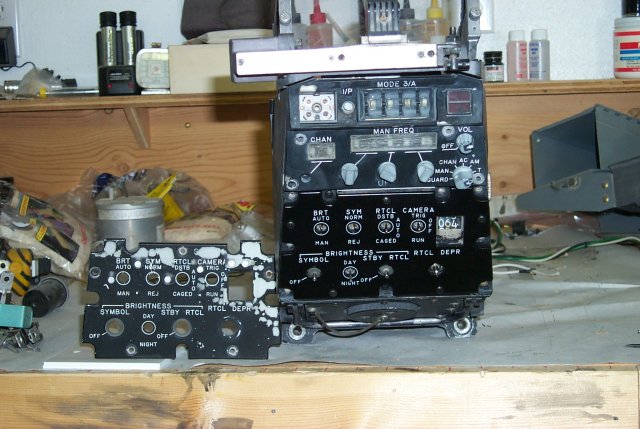
The old lightplate is shown on the left. Pretty sad looking, isn't it?
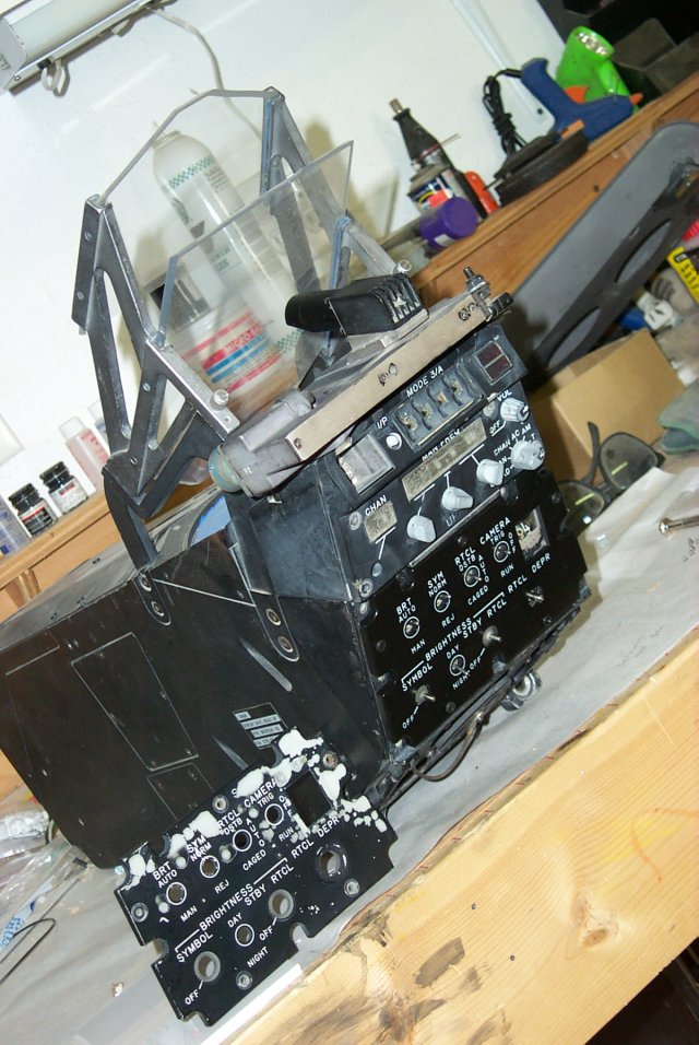
Here's a better shot of the HUD. The HUD camera has been installed for this picture. If I can get it to work, I'll leave it there. Otherwise, it'll get removed.
The UHF radio control head that was on the HUD when I got it is in pretty rough shape. Fortunately, I've got a replacement for it that is in MUCH better condition, although the Channel selector control shaft has been broken on this one as well.
Another new goodie that I haven't mentioned yet is the brand new Fuel Quantity indicator I got. It was built by Malwin Electronics for specific use in a
flight simulator. The indicator can be driven by the R&R Electronics Gauge and Meter module. In fact, Matt Wietlispach's flight simulator uses this same instrument. His website is here.
Here's a picture of the new indicator:
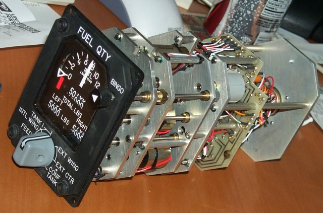
I'd like to thank Matt for his help, advice and generosity. Without him, this project would be much farther behind than it is today. Thanks Matt!
July 20th, 2004
A gentleman from The Netherlands contacted me a short time ago with an amazing thing! He said he had footage of my F-15C during it's last flight and subsequent accident! Many thanks to Michael Pols for supplying this fantastic footage to me! This first link is of the last moments of the flight demonstration, followed by the crash demonstration. :) Baby's Last Steps The second link is a short walk-around done by the local Dutch TV crew: Wreck walk-around Thanks to Roy Coates for hosting the movie files for me.
June 11th, 2004
In the Operation section, there is a new document titled The F15 Flight Control System that you might want to check out. It's the first of the Product Support Digest articles that I'm reprinting from the Eagle Talk Digests that I have. It gives a very clear overview of how the flight control system in the F-15 works.
May 11th, 2004
Added a banner for a neat new F-15E research website that's based in Hungary. Great stuff there!
January 1st, 2004
Happy New Year everyone! I've got some good updates today. The first covers the new Instructor Console that is under construction. You can check it out here. Next up are details on the AC power system that the simulator uses! This has been in the works for quite a while, but I only recently got the time to write it up for you. You can head over to the Tech section or click here. This:
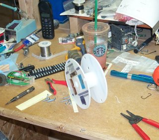
...is the third 1,000 foot spool of wire I've used so far. That's right folks, the F-15C simulator project has officially consumed 3,000 feet of signal wire. :) [/center][center]
October 12th, 2004
Minor update. Moved one of the banners to the bottom of the news page.
The @f15sim.com email is fixed. I'd accidentally trashed the mx record. *d'oh*
September 12th, 2004
As promised, I've got more goodies from the Eagle Talk digests online. The new sections cover the hydraulic system, the hydro-mechanical control system and the directional control system. There are 5 more parts to the series and I'll get them online soon!
You'll also note a big rework of the Project News page. I hadn't realized how large the page was so I decided to cut it down a bit and move prior year updates to their own page. You can find them here or follow the link at the bottom of this page.
August 7th 2004
I got a nice package from the Washington State Dept. of Transportation today.
I'm having difficulty deciding between, "W00t!", "This is cool." or "This rawks!"
*ahem*
...now if I only had the time to work on the silly thing. *wistful sigh* July 31st, 2004
Here's a couple of pictures that show the new HUD control panel lightplate that Peter Cos of Flightdeck Solutions made for me.
The old lightplate is shown on the left. Pretty sad looking, isn't it?
Here's a better shot of the HUD. The HUD camera has been installed for this picture. If I can get it to work, I'll leave it there. Otherwise, it'll get removed.
The UHF radio control head that was on the HUD when I got it is in pretty rough shape. Fortunately, I've got a replacement for it that is in MUCH better condition, although the Channel selector control shaft has been broken on this one as well.
Another new goodie that I haven't mentioned yet is the brand new Fuel Quantity indicator I got. It was built by Malwin Electronics for specific use in a
flight simulator. The indicator can be driven by the R&R Electronics Gauge and Meter module. In fact, Matt Wietlispach's flight simulator uses this same instrument. His website is here.
Here's a picture of the new indicator:
I'd like to thank Matt for his help, advice and generosity. Without him, this project would be much farther behind than it is today. Thanks Matt!
July 20th, 2004
A gentleman from The Netherlands contacted me a short time ago with an amazing thing! He said he had footage of my F-15C during it's last flight and subsequent accident! Many thanks to Michael Pols for supplying this fantastic footage to me! This first link is of the last moments of the flight demonstration, followed by the crash demonstration. :) Baby's Last Steps The second link is a short walk-around done by the local Dutch TV crew: Wreck walk-around Thanks to Roy Coates for hosting the movie files for me.
June 11th, 2004
In the Operation section, there is a new document titled The F15 Flight Control System that you might want to check out. It's the first of the Product Support Digest articles that I'm reprinting from the Eagle Talk Digests that I have. It gives a very clear overview of how the flight control system in the F-15 works.
May 11th, 2004
Added a banner for a neat new F-15E research website that's based in Hungary. Great stuff there!
January 1st, 2004
Happy New Year everyone! I've got some good updates today. The first covers the new Instructor Console that is under construction. You can check it out here. Next up are details on the AC power system that the simulator uses! This has been in the works for quite a while, but I only recently got the time to write it up for you. You can head over to the Tech section or click here. This:
...is the third 1,000 foot spool of wire I've used so far. That's right folks, the F-15C simulator project has officially consumed 3,000 feet of signal wire. :) [/center]
October 12th, 2004
Minor update. Moved one of the banners to the bottom of the news page.
The @f15sim.com email is fixed. I'd accidentally trashed the mx record. *d'oh*
September 12th, 2004
As promised, I've got more goodies from the Eagle Talk digests online. The new sections cover the hydraulic system, the hydro-mechanical control system and the directional control system. There are 5 more parts to the series and I'll get them online soon!
You'll also note a big rework of the Project News page. I hadn't realized how large the page was so I decided to cut it down a bit and move prior year updates to their own page. You can find them here or follow the link at the bottom of this page.
August 7th 2004
I got a nice package from the Washington State Dept. of Transportation today.
I'm having difficulty deciding between, "W00t!", "This is cool." or "This rawks!"
*ahem*
...now if I only had the time to work on the silly thing. *wistful sigh* July 31st, 2004
Here's a couple of pictures that show the new HUD control panel lightplate that Peter Cos of Flightdeck Solutions made for me.
The old lightplate is shown on the left. Pretty sad looking, isn't it?
Here's a better shot of the HUD. The HUD camera has been installed for this picture. If I can get it to work, I'll leave it there. Otherwise, it'll get removed.
The UHF radio control head that was on the HUD when I got it is in pretty rough shape. Fortunately, I've got a replacement for it that is in MUCH better condition, although the Channel selector control shaft has been broken on this one as well.
Another new goodie that I haven't mentioned yet is the brand new Fuel Quantity indicator I got. It was built by Malwin Electronics for specific use in a
flight simulator. The indicator can be driven by the R&R Electronics Gauge and Meter module. In fact, Matt Wietlispach's flight simulator uses this same instrument. His website is here.
Here's a picture of the new indicator:
I'd like to thank Matt for his help, advice and generosity. Without him, this project would be much farther behind than it is today. Thanks Matt!
July 20th, 2004
A gentleman from The Netherlands contacted me a short time ago with an amazing thing! He said he had footage of my F-15C during it's last flight and subsequent accident! Many thanks to Michael Pols for supplying this fantastic footage to me! This first link is of the last moments of the flight demonstration, followed by the crash demonstration. :) Baby's Last Steps The second link is a short walk-around done by the local Dutch TV crew: Wreck walk-around Thanks to Roy Coates for hosting the movie files for me.
June 11th, 2004
In the Operation section, there is a new document titled The F15 Flight Control System that you might want to check out. It's the first of the Product Support Digest articles that I'm reprinting from the Eagle Talk Digests that I have. It gives a very clear overview of how the flight control system in the F-15 works.
May 11th, 2004
Added a banner for a neat new F-15E research website that's based in Hungary. Great stuff there!
January 1st, 2004
Happy New Year everyone! I've got some good updates today. The first covers the new Instructor Console that is under construction. You can check it out here. Next up are details on the AC power system that the simulator uses! This has been in the works for quite a while, but I only recently got the time to write it up for you. You can head over to the Tech section or click here. This:
...is the third 1,000 foot spool of wire I've used so far. That's right folks, the F-15C simulator project has officially consumed 3,000 feet of signal wire. :) [/center][center]
October 12th, 2004
Minor update. Moved one of the banners to the bottom of the news page.
The @f15sim.com email is fixed. I'd accidentally trashed the mx record. *d'oh*
September 12th, 2004
As promised, I've got more goodies from the Eagle Talk digests online. The new sections cover the hydraulic system, the hydro-mechanical control system and the directional control system. There are 5 more parts to the series and I'll get them online soon!
You'll also note a big rework of the Project News page. I hadn't realized how large the page was so I decided to cut it down a bit and move prior year updates to their own page. You can find them here or follow the link at the bottom of this page.
August 7th 2004
I got a nice package from the Washington State Dept. of Transportation today.
I'm having difficulty deciding between, "W00t!", "This is cool." or "This rawks!"
*ahem*
...now if I only had the time to work on the silly thing. *wistful sigh* July 31st, 2004
Here's a couple of pictures that show the new HUD control panel lightplate that Peter Cos of Flightdeck Solutions made for me.
The old lightplate is shown on the left. Pretty sad looking, isn't it?
Here's a better shot of the HUD. The HUD camera has been installed for this picture. If I can get it to work, I'll leave it there. Otherwise, it'll get removed.
The UHF radio control head that was on the HUD when I got it is in pretty rough shape. Fortunately, I've got a replacement for it that is in MUCH better condition, although the Channel selector control shaft has been broken on this one as well.
Another new goodie that I haven't mentioned yet is the brand new Fuel Quantity indicator I got. It was built by Malwin Electronics for specific use in a
flight simulator. The indicator can be driven by the R&R Electronics Gauge and Meter module. In fact, Matt Wietlispach's flight simulator uses this same instrument. His website is here.
Here's a picture of the new indicator:
I'd like to thank Matt for his help, advice and generosity. Without him, this project would be much farther behind than it is today. Thanks Matt!
July 20th, 2004
A gentleman from The Netherlands contacted me a short time ago with an amazing thing! He said he had footage of my F-15C during it's last flight and subsequent accident! Many thanks to Michael Pols for supplying this fantastic footage to me! This first link is of the last moments of the flight demonstration, followed by the crash demonstration. :) Baby's Last Steps The second link is a short walk-around done by the local Dutch TV crew: Wreck walk-around Thanks to Roy Coates for hosting the movie files for me.
June 11th, 2004
In the Operation section, there is a new document titled The F15 Flight Control System that you might want to check out. It's the first of the Product Support Digest articles that I'm reprinting from the Eagle Talk Digests that I have. It gives a very clear overview of how the flight control system in the F-15 works.
May 11th, 2004
Added a banner for a neat new F-15E research website that's based in Hungary. Great stuff there!
January 1st, 2004
Happy New Year everyone! I've got some good updates today. The first covers the new Instructor Console that is under construction. You can check it out here. Next up are details on the AC power system that the simulator uses! This has been in the works for quite a while, but I only recently got the time to write it up for you. You can head over to the Tech section or click here. This:
...is the third 1,000 foot spool of wire I've used so far. That's right folks, the F-15C simulator project has officially consumed 3,000 feet of signal wire. :) [/center]
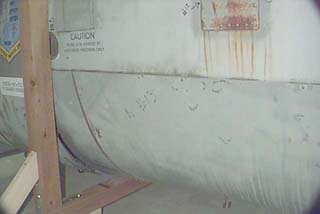
[center]<B>Delivery - September 7th, 2000 </B>

Here's the F-15 in the new transport cradle I built for it. Each cradle is made from a single 8 foot long Wolmanized 4x4 with two 4 foot 4x4 uprights and two 4 foot 4x4 outriggers. There are six 2.5 inch castors on each cradle. The high number of casters was required to make sure the cradle had the needed stability as well as the necessary weight capacity. On the cradles the cockpit is surprisingly easy to move, even for a single person.
I must admit that up until it was sitting in my driveway, I really didn't believe that I'd managed to get an F-15 cockpit.
I'm quite sure that in the coming years, I'll be continually pinching myself to make sure it's all real.

Initially, I was concerned that the ejection seat rails were going to be too high to pass underneath the garage door frame. My friend Dave is currently in the process of unbolting the left hand rail.

What can I say? :)

Another pic of Dave working on that ejection seat rail....but wait!

On a hunch, I had Dave stop working on the rail. I told him to crouch down and push the cockpit into the shop. As you can see from the picture, it cleared that white strip (NOT the seal) by less than an eighth of an inch!
Dave can now tell his friends that he's had a ride in an F-15C, just as long as he doesn't relate the circumstances...

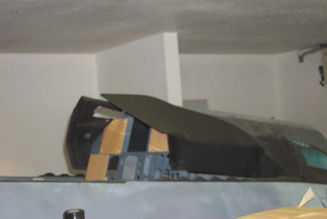
Originally, I had thought that I was looking at removing the 50+ bolts that held the forward wind screen to the fuselage. However, it seems that this windscreen wasn't the original that came with the jet. After finding only four bolts to remove, the wind screen came right off. I found a white ink stamp underneath the frame that identified it as being for an F-15A.
The wind screen itself is over an inch thick and the whole assembly weighs in at about 100lbs.

This is a tilted picture of the nose gear well. The pair of black conduits are waveguides for the radar system.
A waveguide is basically a specially shaped hollow pipe that radio energy flows through, much like water through a pipe.
The blueish colored pipe in the lower right hand corner of the picture is a hot air pipe that leads up to a connector right below the front end of the wind screen. It's used for defrosting/defogging the glass.
The other mechanisms visible are related to lowering the nose gear as well as operating the forward nose gear door.

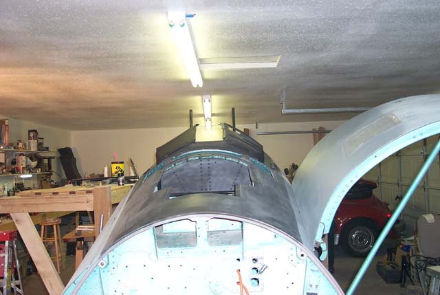
Here is a better view of the linkage that operates the forward nose gear door. The door itself is still in place.

In this long shot, you can see all the various lines and linkages that run through the nose gear bay.
My very own F-15C. I _still_ can't believe it!
Gene Buckle September 8th, 2000 [/center]
Here's the F-15 in the new transport cradle I built for it. Each cradle is made from a single 8 foot long Wolmanized 4x4 with two 4 foot 4x4 uprights and two 4 foot 4x4 outriggers. There are six 2.5 inch castors on each cradle. The high number of casters was required to make sure the cradle had the needed stability as well as the necessary weight capacity. On the cradles the cockpit is surprisingly easy to move, even for a single person.
I must admit that up until it was sitting in my driveway, I really didn't believe that I'd managed to get an F-15 cockpit.
I'm quite sure that in the coming years, I'll be continually pinching myself to make sure it's all real.
Initially, I was concerned that the ejection seat rails were going to be too high to pass underneath the garage door frame. My friend Dave is currently in the process of unbolting the left hand rail.
What can I say? :)
Another pic of Dave working on that ejection seat rail....but wait!
On a hunch, I had Dave stop working on the rail. I told him to crouch down and push the cockpit into the shop. As you can see from the picture, it cleared that white strip (NOT the seal) by less than an eighth of an inch!
Dave can now tell his friends that he's had a ride in an F-15C, just as long as he doesn't relate the circumstances...
Originally, I had thought that I was looking at removing the 50+ bolts that held the forward wind screen to the fuselage. However, it seems that this windscreen wasn't the original that came with the jet. After finding only four bolts to remove, the wind screen came right off. I found a white ink stamp underneath the frame that identified it as being for an F-15A.
The wind screen itself is over an inch thick and the whole assembly weighs in at about 100lbs.
This is a tilted picture of the nose gear well. The pair of black conduits are waveguides for the radar system.
A waveguide is basically a specially shaped hollow pipe that radio energy flows through, much like water through a pipe.
The blueish colored pipe in the lower right hand corner of the picture is a hot air pipe that leads up to a connector right below the front end of the wind screen. It's used for defrosting/defogging the glass.
The other mechanisms visible are related to lowering the nose gear as well as operating the forward nose gear door.
Here is a better view of the linkage that operates the forward nose gear door. The door itself is still in place.
In this long shot, you can see all the various lines and linkages that run through the nose gear bay.
My very own F-15C. I _still_ can't believe it!
Gene Buckle September 8th, 2000 [/center]
[此贴子已经被作者于2005-1-30 19:24:14编辑过]
<P> 加为精华,我方应该对对方机种有详细了解。</P>
请楼主翻译一下.[em01][em01][em01][em01]
[center]尊重斑竹的要超级大本营军事论坛 求:我将全面展开F-15C的所有细节,各位军事爱好者和军事专家及各位大侠帮帮忙吧!这可是好东西也!!!
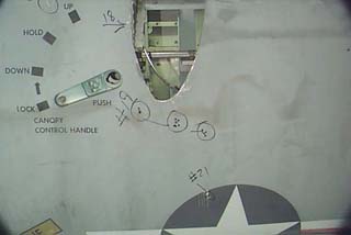
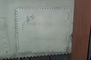
This is a photo illustration of the various repairs that need to be made before I can start work on the "fun" stuff. I must apologize for the condition of the photos - I was using a VERY low res digital camera for these shots.
Punched hole - filled with bondo
Status: [Done]
Pitot Probe assembly. A cover plate needs to be made to close this.
Status: [Not Started]
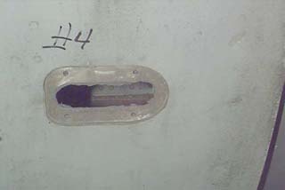
Requires new cover plate.
Status: [Not Started]
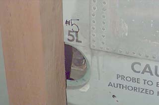
AOA vane assembly. This will be covered with a smooth plate until I obtain a surplus AOA vane to install here.
Status: [Not Started]
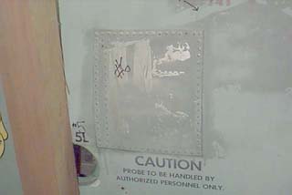
Pre-existing rough patch. This needs to be cleaned up and painted.
Status: [Done]
 [/center]
This is a photo illustration of the various repairs that need to be made before I can start work on the "fun" stuff. I must apologize for the condition of the photos - I was using a VERY low res digital camera for these shots.
Punched hole - filled with bondo
Status: [Done]
Pitot Probe assembly. A cover plate needs to be made to close this.
Status: [Not Started]
Requires new cover plate.
Status: [Not Started]
AOA vane assembly. This will be covered with a smooth plate until I obtain a surplus AOA vane to install here.
Status: [Not Started]
Pre-existing rough patch. This needs to be cleaned up and painted.
Status: [Done]
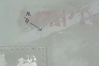
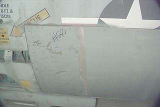
[/center][center]Deep scratch in the metal. Fill with body putty.
Status: [Done]
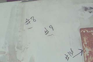
Two small corner tears in the fuselage skin (#'s 8 and 9). Needs to be filled with body putty.
Status: [Done]
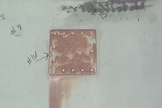
This is a ferrous patch that has rusted quite badly. Needs to be cleaned up and painted. Rust marks underneath the patch needs to be cleaned as well.
Status: [Done]
Left forward avionics bay is covered by a large sheet of poorly attached aluminum. This needs to be removed.
Status: [Done]
Small dent that can easily be filled with body putty.
Status: [Done]
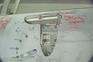
Huge, gaping hole in the fuselage. I have no idea why this was done, but it's going to require extensive work to repair it.
Status: [Done]
 [/center]
Status: [Done]
Two small corner tears in the fuselage skin (#'s 8 and 9). Needs to be filled with body putty.
Status: [Done]
This is a ferrous patch that has rusted quite badly. Needs to be cleaned up and painted. Rust marks underneath the patch needs to be cleaned as well.
Status: [Done]
Left forward avionics bay is covered by a large sheet of poorly attached aluminum. This needs to be removed.
Status: [Done]
Small dent that can easily be filled with body putty.
Status: [Done]
Huge, gaping hole in the fuselage. I have no idea why this was done, but it's going to require extensive work to repair it.
Status: [Done]
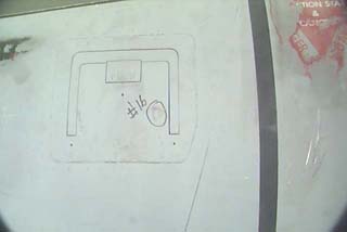
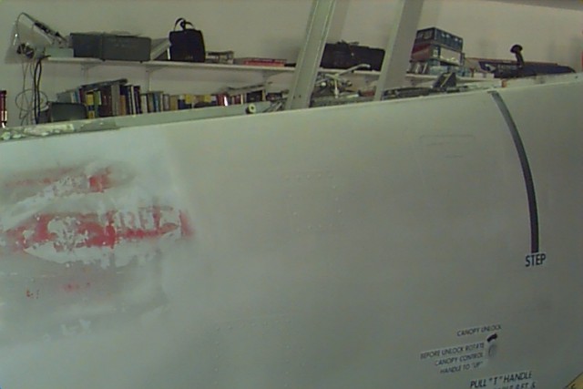
[/center][center]Series of drilled holes. Fill with body putty.
Status: [Done]
Rear avionics bay cover. Again, like it's forward counterpart is made of sheet aluminum that's been poorly attached. It needs to be removed.
Status: [Done]
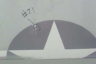
Small rivet hole that needs to be filled.
Status: [Done]
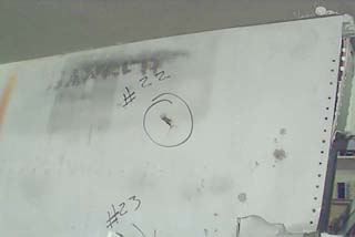
Punch/tear in aft of fuselage. Needs to be trimmed and filled.
Status: [Done]
Big hole punched through skin (#25) and silicone caulk encrusted skin patch (#27). Hole needs to be filled and the patch needs to be drilled off and replaced.
Status: [Done]
Series of "slices" in the skin. Area is also pushed in. This will end up being filled with body putty.
Status: [Done]
Patch needs cleanup and repair.
Status: [Done]
Rivet holes that need to be filled.
Status: [Done]
Patch needs to be cleaned up and repaired.
Status: [Done]
[/center]
Status: [Done]
Rear avionics bay cover. Again, like it's forward counterpart is made of sheet aluminum that's been poorly attached. It needs to be removed.
Status: [Done]
Small rivet hole that needs to be filled.
Status: [Done]
Punch/tear in aft of fuselage. Needs to be trimmed and filled.
Status: [Done]
Big hole punched through skin (#25) and silicone caulk encrusted skin patch (#27). Hole needs to be filled and the patch needs to be drilled off and replaced.
Status: [Done]
Series of "slices" in the skin. Area is also pushed in. This will end up being filled with body putty.
Status: [Done]
Patch needs cleanup and repair.
Status: [Done]
Rivet holes that need to be filled.
Status: [Done]
Patch needs to be cleaned up and repaired.
Status: [Done]
[/center]
[center]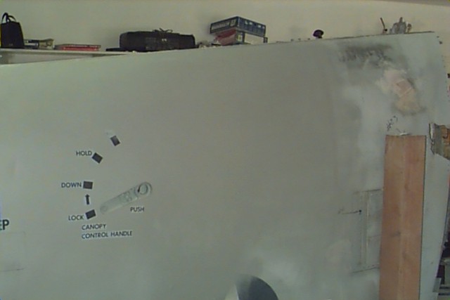
This was the largest repair made to the fuselage. Compare with the gaping hole it used to have:
As you can see, it looks a LOT nicer with the hole fixed. :) The hole you see is over 2 feet high and roughly
18 inches wide. Below is another shot of the repaired area.
This is the work that was done on the aft end on the right side. I don't have a picture of it finished and primered
unfortunately.
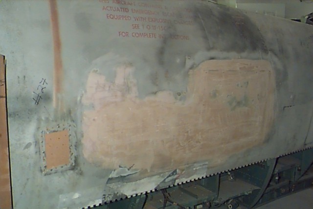
Here is what it used to look like:
It's kind of difficult to see in this image, but there were over a dozen saw cuts made to the skin and
large areas were bowed in. It took a huge amount of Bondo to fill this in properly. [/center]
This was the largest repair made to the fuselage. Compare with the gaping hole it used to have:
As you can see, it looks a LOT nicer with the hole fixed. :) The hole you see is over 2 feet high and roughly
18 inches wide. Below is another shot of the repaired area.
This is the work that was done on the aft end on the right side. I don't have a picture of it finished and primered
unfortunately.
Here is what it used to look like:
It's kind of difficult to see in this image, but there were over a dozen saw cuts made to the skin and
large areas were bowed in. It took a huge amount of Bondo to fill this in properly. [/center]
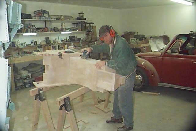
[center]F-15C - Making the Right Glareshield
You'd think that heat forming acrylic would be a great big pain in the butt,
wouldn't you? That isn't necessarily so.
Rob and I had been scratching our heads on how to build a good replica
of a glareshield half we'd never seen. I had gotten my hands on the left
hand half a couple of months ago, so we knew how long it had to be.
Eventually, Rob started working on a 1/8" MDF replica of it. This turned
out ok, but wasn't exactly what was needed.
This last Saturday, we started working on it again after a long hiatus.
Rob built another template to use and we set it into position over the
right instrument panel half. We wanted to use a 1/8" sheet of Lexan to
create the new glareshield half. After trying a couple of different methods
including a pair of 1000 Watt lamps, we got stumped as to what we could use
to form the plastic.
After wandering around the shop a bit, I said to Rob: "Look, the only thing
I have left that would generate a lot of heat is the propane space heater".
I'll be a son of a bitch. Necessity IS the mother of invention! Hehe.
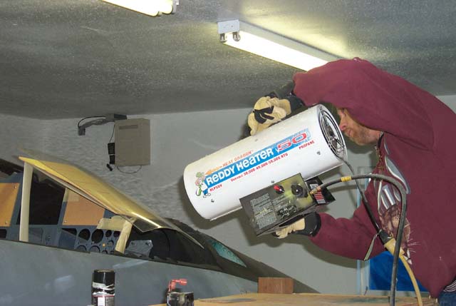
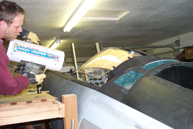
Yes, he's doing exactly what you think he is. A propate space heater IS
a hand-held tool when the need arises! (Don't try this at home kids, we're
Professionals of Mechanical Improvisation)
It looks pretty crazy alright. As Rob heated the plastic I (wearing gloves)
formed the plastic around the makeshift mold by hand. Eventually I used a
short plywood "stick" to keep from getting burned any more than I already was.
(Ok, not exactly burned, but "well heated" to say the least.)
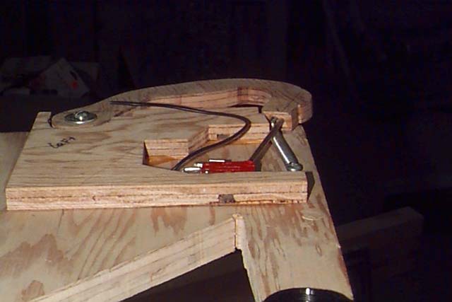
Below is the result
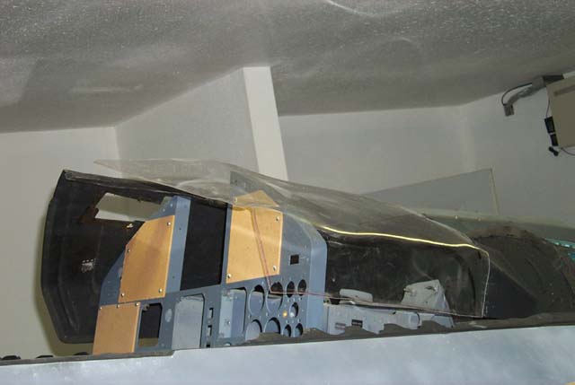
The result was pretty impressive considering the methods we used to get to this
point.
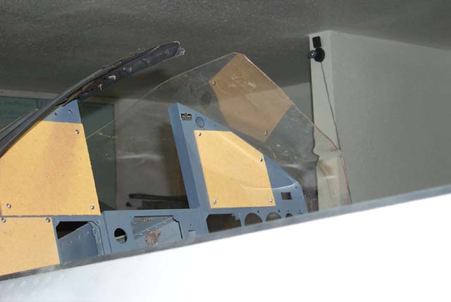
Here is what it looks like painted up and and re-installed:
There is still some finish work to be done, such as adding the rubber coaming
to the leading edge of the glareshield half and making hold-down brackets so
it will grip the instrument panel. All in all, I'm impressed with the result![/center]
You'd think that heat forming acrylic would be a great big pain in the butt,
wouldn't you? That isn't necessarily so.
Rob and I had been scratching our heads on how to build a good replica
of a glareshield half we'd never seen. I had gotten my hands on the left
hand half a couple of months ago, so we knew how long it had to be.
Eventually, Rob started working on a 1/8" MDF replica of it. This turned
out ok, but wasn't exactly what was needed.
This last Saturday, we started working on it again after a long hiatus.
Rob built another template to use and we set it into position over the
right instrument panel half. We wanted to use a 1/8" sheet of Lexan to
create the new glareshield half. After trying a couple of different methods
including a pair of 1000 Watt lamps, we got stumped as to what we could use
to form the plastic.
After wandering around the shop a bit, I said to Rob: "Look, the only thing
I have left that would generate a lot of heat is the propane space heater".
I'll be a son of a bitch. Necessity IS the mother of invention! Hehe.
Yes, he's doing exactly what you think he is. A propate space heater IS
a hand-held tool when the need arises! (Don't try this at home kids, we're
Professionals of Mechanical Improvisation)
It looks pretty crazy alright. As Rob heated the plastic I (wearing gloves)
formed the plastic around the makeshift mold by hand. Eventually I used a
short plywood "stick" to keep from getting burned any more than I already was.
(Ok, not exactly burned, but "well heated" to say the least.)
Below is the result
The result was pretty impressive considering the methods we used to get to this
point.
Here is what it looks like painted up and and re-installed:
There is still some finish work to be done, such as adding the rubber coaming
to the leading edge of the glareshield half and making hold-down brackets so
it will grip the instrument panel. All in all, I'm impressed with the result![/center]
[center] July 29th, 2001
Today I spent some needed time finishing the throttle quadrant rebuild.
I needed to rewire the switch assemblies on both grips to allow easier
interfacing to the EPIC input matrix.
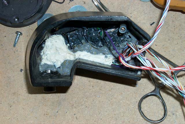
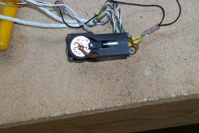
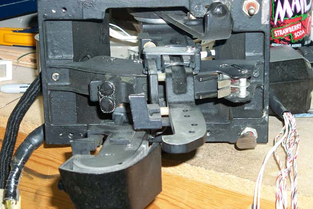
This is what the inside of the left throttle grip looks like.
To prevent corrosion of the switch wiring everything has been potted with
a gray RTV silicone caulking. The white area is new RTV that was used
when one of the switches was replaced at the depot.
Unlike what I did for the right grip, I left all the original wiring in
place. This was done to avoid all the hassles of digging out the RTV
and burning through the protective coating that the solder terminals
had applied to them. During the rewiring work on the right grip, I destroyed
the RETICLE STIFFEN/SRM REJECT switch in my attempts to remove it.
Fortunately, I had a nearly exact replacement for it in my bench stock.
I got lucky once. Lesson learned.
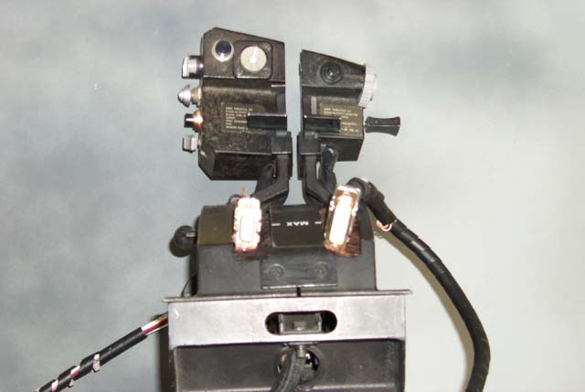
Here is what the "working" face of the left throttle grip looks like
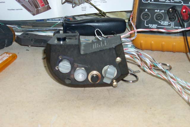
From right to left, the switches are:
WEAPON SELECT, EWWS INTERROGATE, SPEED BRAKE, UHF1/UHF2 TRANSMIT,
IFF INTERROGATE/AIM9 BORESIGHT, and TARGET DESIGNATION CONTROL.
The Target Designation Control that's used in the F-15C is electrically
similar to the F-16 flight control system in that they both use measurement
of force to translate motion into electronic signals.
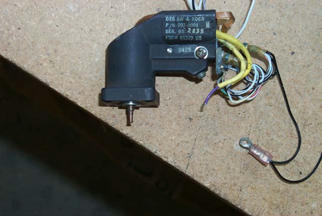
This is what the TDC looks like after being removed from the grip. The
shaft that sticks out is where the cursor "button" attaches to.
In this image, you see the back of the TDC unit. The round assembly is the
force sensor portion of the control. This translates finger pressure into
cursor movement on the radar display. To the right, you can just make out
the pushbutton that tells the radar system to lock on to the selected
target. When you press on the cursor control, the whole assembly slides
back to press this button. It's actually a pretty neat design.
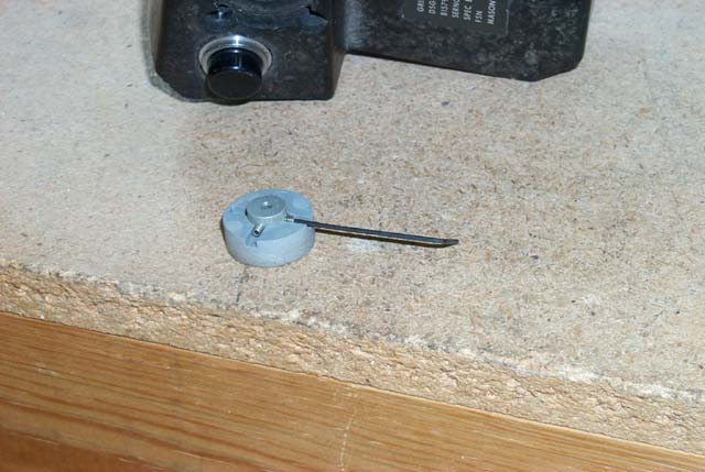
This is what the cursor button itself looks like. This was a pain to remove
due to the requirement for a 0.028 hex wrench to remove it. Fortunately,
Robbi was able to find one at Tacoma Screw Products.
Prior to soldering up the DB15 connector to the wiring harness, I had to
disassemble the upper portion of the quadrant so I could route the wiring in
the location used by the old wiring harness.
Here is the throttle completely re-assembled with the new wiring harnesses on
display. The right grip uses a female DB9 connector and the left uses a DB15.
The TDC cursor controller is not connected right now due to the high cost
of the signal amplifiers needed to properly use it.
Back to the Tech Index[/center]
Today I spent some needed time finishing the throttle quadrant rebuild.
I needed to rewire the switch assemblies on both grips to allow easier
interfacing to the EPIC input matrix.
This is what the inside of the left throttle grip looks like.
To prevent corrosion of the switch wiring everything has been potted with
a gray RTV silicone caulking. The white area is new RTV that was used
when one of the switches was replaced at the depot.
Unlike what I did for the right grip, I left all the original wiring in
place. This was done to avoid all the hassles of digging out the RTV
and burning through the protective coating that the solder terminals
had applied to them. During the rewiring work on the right grip, I destroyed
the RETICLE STIFFEN/SRM REJECT switch in my attempts to remove it.
Fortunately, I had a nearly exact replacement for it in my bench stock.
I got lucky once. Lesson learned.
Here is what the "working" face of the left throttle grip looks like
From right to left, the switches are:
WEAPON SELECT, EWWS INTERROGATE, SPEED BRAKE, UHF1/UHF2 TRANSMIT,
IFF INTERROGATE/AIM9 BORESIGHT, and TARGET DESIGNATION CONTROL.
The Target Designation Control that's used in the F-15C is electrically
similar to the F-16 flight control system in that they both use measurement
of force to translate motion into electronic signals.
This is what the TDC looks like after being removed from the grip. The
shaft that sticks out is where the cursor "button" attaches to.
In this image, you see the back of the TDC unit. The round assembly is the
force sensor portion of the control. This translates finger pressure into
cursor movement on the radar display. To the right, you can just make out
the pushbutton that tells the radar system to lock on to the selected
target. When you press on the cursor control, the whole assembly slides
back to press this button. It's actually a pretty neat design.
This is what the cursor button itself looks like. This was a pain to remove
due to the requirement for a 0.028 hex wrench to remove it. Fortunately,
Robbi was able to find one at Tacoma Screw Products.
Prior to soldering up the DB15 connector to the wiring harness, I had to
disassemble the upper portion of the quadrant so I could route the wiring in
the location used by the old wiring harness.
Here is the throttle completely re-assembled with the new wiring harnesses on
display. The right grip uses a female DB9 connector and the left uses a DB15.
The TDC cursor controller is not connected right now due to the high cost
of the signal amplifiers needed to properly use it.
Back to the Tech Index[/center]
[此贴子已经被作者于2005-2-3 12:35:36编辑过]
[此贴子已经被作者于2005-2-3 13:22:47编辑过]
<P>Gene Buckle September 8th, 2000
Initial Recovery
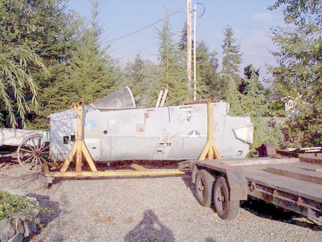
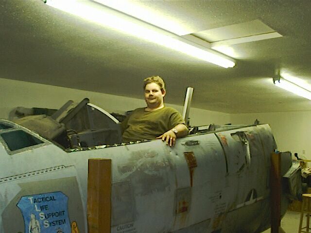
这是这个坐舱从Olympia空军博物馆转移到作者家中的最初状况
这个坐舱看上去在室外很久了,它最近的用途,看上去是作为空军修理人员修理战伤的教具,因为这个坐舱上面有很多地方看上去像是近距离的枪伤的结果,也能够发现蒙皮修补的痕迹。
这段机身大概有15英尺长,从底部到前风挡弧顶大约有7英尺高,总重约1500磅。
这段机身的确切历史仍然是迷雾重重。作者所知道的,仅仅是它前一位主人知道的那么一点,再加上作者本人从这个坐舱上面读到的。这个坐舱是从Tacoma(塔科马,华盛顿州西部港口城市)的McChord空军基地买来的,当时McChord是一个F-15中队的基地。从彩色的美军机徽来看,这个飞机是在1986年之前报废的,因为从1986年之后,美国空军在F-15和其他飞机上,就使用单色的机徽了。
在1980年代的中期,这段机身用在“战术生命保障系统”这个计划里面,这个计划又可称作“战术飞行保障系统”。作者本来以为他的这个坐舱是用来做飞行试验的,但后来的调查发现,在爱德华兹空军基地的机体并没有报废的。所以作者又把目光投向在TLSS/TFSS项目中做静力实验的空军基地。在布鲁克斯空军基地里,有4个用来做静力实验的坐舱,很有可能作者的这个就是其中之一。
在此,要感谢爱德华兹空军基地对外办公室的技术军士Christopher Ball和历史研究所的Ray Puffer博士,在他们的帮助下作者才了解到以上历史。
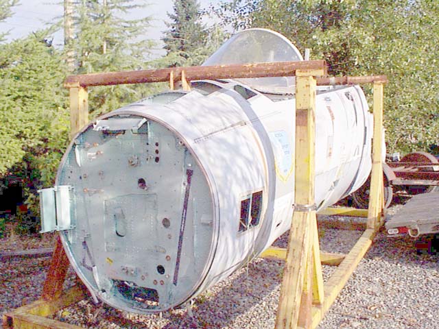
这些黄色的支撑架是在报废的时候,工作人员安装的。它们将被一个新的支架代替,这样所有的航空电子设备舱和检查口都可以被触及。
照片上可以看到雷达是如何安装到机头上的。
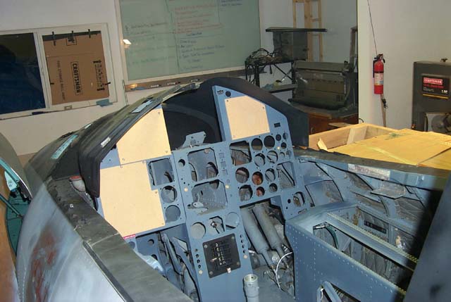
在机身的第一个隔框上,安装了一块1/4英寸厚的金属板,这里将要安装新的支架,使得两个前部的航空电子设备舱门能够打开,而不是象照片上面那样被边上的立柱挡着。
机头左边的方形金属是雷达整流罩的铰链。这个铰链将飞机的“头锥”和机身连接在一起,同时使得地勤能够方便地接触到雷达天线和跟踪器。黑色的条子,是储存雷达整流罩打开时的支撑杆的地方。
可以发现,机头上部有几块蒙皮丢失了。这就必须手工重新制作。左边电子设备舱铰链上方的蒙皮也非常糟糕了,需要换新的。电子设备舱门上,也有几个洞需要修理。
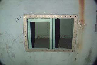
在前风挡前面的开口,是用来取下连接前风挡和机身的螺栓的。电子设备舱门上面的两个方形开口,原来是用来安装空速管的,在左侧(面对机头站)的设备舱门上也有这样的一组开口。
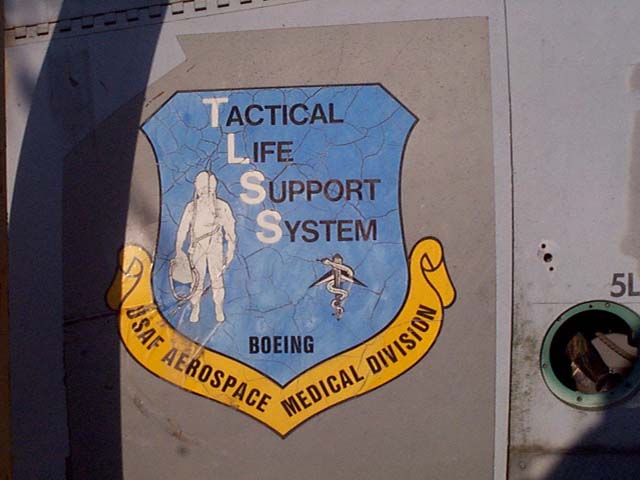
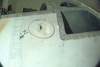
这个标志在左右两侧的电子设备舱门上都有。
标志的右边,是左侧的功角传感器的位置。功角传感器基本上可以认为是一个可以自由转动的叶片,它向飞行数据计算机传输叶片相对地平线角度的信息。
</P>
Initial Recovery
这是这个坐舱从Olympia空军博物馆转移到作者家中的最初状况
这个坐舱看上去在室外很久了,它最近的用途,看上去是作为空军修理人员修理战伤的教具,因为这个坐舱上面有很多地方看上去像是近距离的枪伤的结果,也能够发现蒙皮修补的痕迹。
这段机身大概有15英尺长,从底部到前风挡弧顶大约有7英尺高,总重约1500磅。
这段机身的确切历史仍然是迷雾重重。作者所知道的,仅仅是它前一位主人知道的那么一点,再加上作者本人从这个坐舱上面读到的。这个坐舱是从Tacoma(塔科马,华盛顿州西部港口城市)的McChord空军基地买来的,当时McChord是一个F-15中队的基地。从彩色的美军机徽来看,这个飞机是在1986年之前报废的,因为从1986年之后,美国空军在F-15和其他飞机上,就使用单色的机徽了。
在1980年代的中期,这段机身用在“战术生命保障系统”这个计划里面,这个计划又可称作“战术飞行保障系统”。作者本来以为他的这个坐舱是用来做飞行试验的,但后来的调查发现,在爱德华兹空军基地的机体并没有报废的。所以作者又把目光投向在TLSS/TFSS项目中做静力实验的空军基地。在布鲁克斯空军基地里,有4个用来做静力实验的坐舱,很有可能作者的这个就是其中之一。
在此,要感谢爱德华兹空军基地对外办公室的技术军士Christopher Ball和历史研究所的Ray Puffer博士,在他们的帮助下作者才了解到以上历史。
这些黄色的支撑架是在报废的时候,工作人员安装的。它们将被一个新的支架代替,这样所有的航空电子设备舱和检查口都可以被触及。
照片上可以看到雷达是如何安装到机头上的。
在机身的第一个隔框上,安装了一块1/4英寸厚的金属板,这里将要安装新的支架,使得两个前部的航空电子设备舱门能够打开,而不是象照片上面那样被边上的立柱挡着。
机头左边的方形金属是雷达整流罩的铰链。这个铰链将飞机的“头锥”和机身连接在一起,同时使得地勤能够方便地接触到雷达天线和跟踪器。黑色的条子,是储存雷达整流罩打开时的支撑杆的地方。
可以发现,机头上部有几块蒙皮丢失了。这就必须手工重新制作。左边电子设备舱铰链上方的蒙皮也非常糟糕了,需要换新的。电子设备舱门上,也有几个洞需要修理。
在前风挡前面的开口,是用来取下连接前风挡和机身的螺栓的。电子设备舱门上面的两个方形开口,原来是用来安装空速管的,在左侧(面对机头站)的设备舱门上也有这样的一组开口。
这个标志在左右两侧的电子设备舱门上都有。
标志的右边,是左侧的功角传感器的位置。功角传感器基本上可以认为是一个可以自由转动的叶片,它向飞行数据计算机传输叶片相对地平线角度的信息。
</P>
在改装成模拟器(我看是大型游戏机)之前,要进行必要的修理。作者使用的相机象素很低,他为此表示歉意。
穿孔——用粘合剂填补
状态:完成
空速管接口,需要一个盖板来封住
状态:未开始
需要新的盖板
状态:未开始
功角传感器:将被一个盖板代替,除非作者能够找到过剩的功角传感器。
状态:未开始
已有的补丁:需要清理并上漆
状态:完成
金属的深刮痕:用腻子填补
状态:完成
穿孔——用粘合剂填补
状态:完成
空速管接口,需要一个盖板来封住
状态:未开始
需要新的盖板
状态:未开始
功角传感器:将被一个盖板代替,除非作者能够找到过剩的功角传感器。
状态:未开始
已有的补丁:需要清理并上漆
状态:完成
金属的深刮痕:用腻子填补
状态:完成
两个刮开口(8#和9#)用腻子填补
状态:完成
这是一个铁质的补丁,严重生锈了。需要清理并上漆。在补丁下方的锈痕同样需要清理并上漆。
状态:完成
左边的前电子设备舱现在被一大块铝板随意地盖着。需要更换
状态:完成
可以用腻子轻松填补的小凹坑
状态:完成
机身上不明来历的巨大的凹坑,需要很多的劳动来修理
状态:完成
[/center]一系列钻出来的孔。用腻子填补
状态:完成
<P>
后电子设备舱,和前电子设备舱同样处理
状态:完成
小铆钉孔需要填补
状态:完成
后部被冲撞/刮擦的痕迹,需要裁剪和填补
状态:完成
蒙皮上的冲击孔以及硬化硅树脂补丁。孔要填补,补丁要取下并重新制作。
状态:完成
蒙皮表面的凹陷,用腻子修补。
状态:完成
补丁需要清理,并修理
状态:完成
需要填补的铆钉孔
状态:完成
补丁需要清理,并修理
状态:完成</P>
后电子设备舱,和前电子设备舱同样处理
状态:完成
小铆钉孔需要填补
状态:完成
后部被冲撞/刮擦的痕迹,需要裁剪和填补
状态:完成
蒙皮上的冲击孔以及硬化硅树脂补丁。孔要填补,补丁要取下并重新制作。
状态:完成
蒙皮表面的凹陷,用腻子修补。
状态:完成
补丁需要清理,并修理
状态:完成
需要填补的铆钉孔
状态:完成
补丁需要清理,并修理
状态:完成</P>
<P>
机身上最大的修补处。下图是修补前
在修复之后看上去好多了吧:)这个洞大约有2英尺高,18英尺宽。下图是修补区域的另外一张照片。
这是左后侧的修补成果。可惜在底漆之后没有留下照片。
这是修补前
照片上看不出来,但是那里有一大堆刮痕,蒙皮也陷下去一大块。看上去像是一大块“邦迪”把它补好的:)</P>
机身上最大的修补处。下图是修补前
在修复之后看上去好多了吧:)这个洞大约有2英尺高,18英尺宽。下图是修补区域的另外一张照片。
这是左后侧的修补成果。可惜在底漆之后没有留下照片。
这是修补前
照片上看不出来,但是那里有一大堆刮痕,蒙皮也陷下去一大块。看上去像是一大块“邦迪”把它补好的:)</P>
very well, u did it pretty good.
[此贴子已经被作者于2005-2-4 8:22:55编辑过]
[此贴子已经被作者于2005-2-4 8:12:56编辑过]
March 27th, 2002
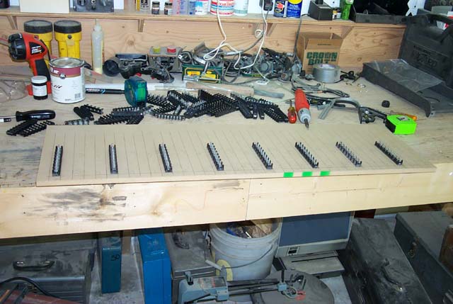
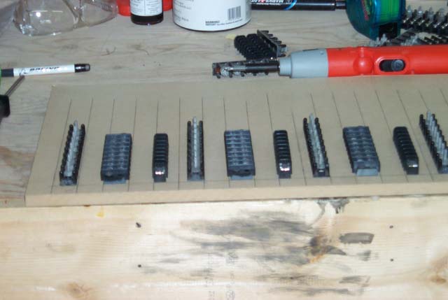
This is the first of 2 large terminal wiring boards. Each board can handle
128 individual switch inputs.
The board itself is 1/2" MDF (Medium Density Fiberboard). The picture here
show the terminal blocks for the "data bit" connections. The terminals
are labeled "DB0" through "DB7" from top to bottom. They'll be wired into
the 8 position terminal block on the EPIC switch matrix board.
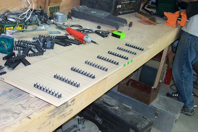
This is the next stage in the process. The dual row terminal block is where
the matrix diode will be mounted to. The diodes are very important - they
are what allows the EPIC matrix scanner to "see" all the switch positions,
even if many (or all!) or in the closed position.
The last terminal block, the "row" block has been installed. Each one of
these are a single row, 8 position terminal block. All 8 positions have been
wired together to create a "bus". Each one of these will connect to one of
the 32 positions on the EPIC switch matrix board. Each one of these is
described as a "Row". Each EPIC switch "module" has 16 rows and thus will
support 128 switches.
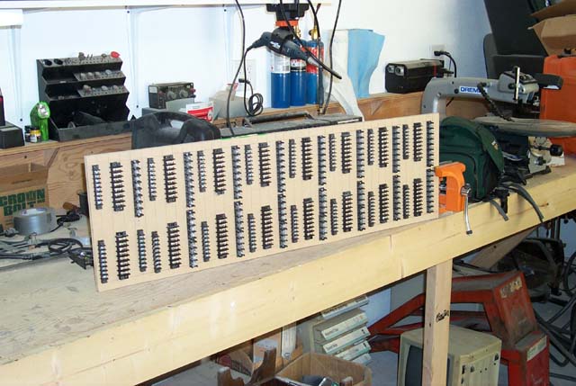
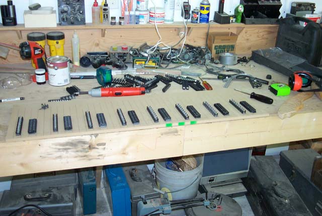
Here is the completed terminal board. As you can see, there are 16 sets of
3 terminal blocks. Each set of 3 is a Module Row. In this case, Module 1,
Row 0 begins at the upper left corner of the board. Row numbers increase
going right. Module 1, Row 8 begins at the lower left corner of the board.
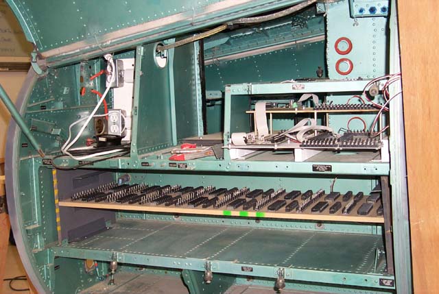
This is what the terminal board looks like in it's "installed" position.
The board slides out for easy maintenance, which is VERY important when
dealing with complex wiring bundles. Eventually the boards will glide on
ball bearing drawer slides, but for this stage of construction, a simple
shelf fit works fine.
This space will hold both of the large terminal boards. A third, much smaller
terminal board will be also located in here (somewhere). The smaller board
will break out the 48 inputs that are present in the scan matrix that's
accessable from the 15 pin joystick connectors on the first expansion module.
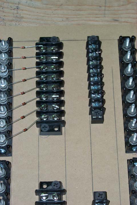
Here is a close-up of how the diodes are installed. The switch wires will go
from the open leg of the dual row terminal block and to the bus-wired 8
position terminal block.
There will be additional wiring to link the diodes as shown in this schematic.
This is the first of 2 large terminal wiring boards. Each board can handle
128 individual switch inputs.
The board itself is 1/2" MDF (Medium Density Fiberboard). The picture here
show the terminal blocks for the "data bit" connections. The terminals
are labeled "DB0" through "DB7" from top to bottom. They'll be wired into
the 8 position terminal block on the EPIC switch matrix board.
This is the next stage in the process. The dual row terminal block is where
the matrix diode will be mounted to. The diodes are very important - they
are what allows the EPIC matrix scanner to "see" all the switch positions,
even if many (or all!) or in the closed position.
The last terminal block, the "row" block has been installed. Each one of
these are a single row, 8 position terminal block. All 8 positions have been
wired together to create a "bus". Each one of these will connect to one of
the 32 positions on the EPIC switch matrix board. Each one of these is
described as a "Row". Each EPIC switch "module" has 16 rows and thus will
support 128 switches.
Here is the completed terminal board. As you can see, there are 16 sets of
3 terminal blocks. Each set of 3 is a Module Row. In this case, Module 1,
Row 0 begins at the upper left corner of the board. Row numbers increase
going right. Module 1, Row 8 begins at the lower left corner of the board.
This is what the terminal board looks like in it's "installed" position.
The board slides out for easy maintenance, which is VERY important when
dealing with complex wiring bundles. Eventually the boards will glide on
ball bearing drawer slides, but for this stage of construction, a simple
shelf fit works fine.
This space will hold both of the large terminal boards. A third, much smaller
terminal board will be also located in here (somewhere). The smaller board
will break out the 48 inputs that are present in the scan matrix that's
accessable from the 15 pin joystick connectors on the first expansion module.
Here is a close-up of how the diodes are installed. The switch wires will go
from the open leg of the dual row terminal block and to the bus-wired 8
position terminal block.
There will be additional wiring to link the diodes as shown in this schematic.
May 22nd, 2002
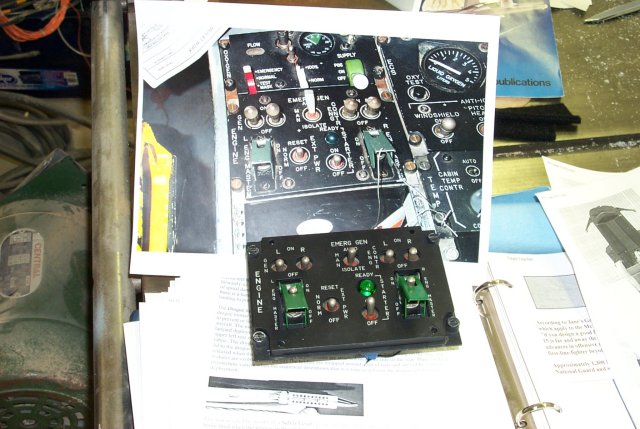
Here's the first scratch built panel for the F-15. The engine control lightplate came from Desktop Simulators. It was a surplus unit from a project they'd previously done with F-15E part/task trainers. The backplate was created from scratch. Rob did a most excellent job in drilling the new mounting plate based upon the holes in the lightplate. This is litterally our first effort on a production panel! It turned out so much better than I think either one of us expected. This of course bodes quite well for all other other panels in the aircraft.
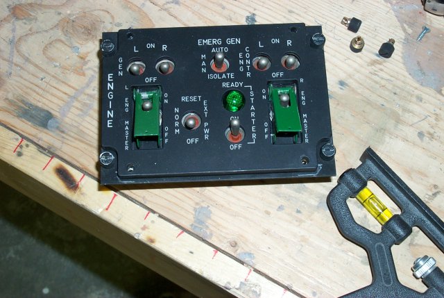
Here is a good comparison between the engine control panel in an active duty
F-15C and the panel that we built. I don't know about you, but I think
ours looks better! :)
When they become available, I'll be adding the "correct" switches to the panel.
The primary impetus at this point is the high cost of some of them. Then
generator and DEEC switches can cost as much as $45 each.
Here's the first scratch built panel for the F-15. The engine control lightplate came from Desktop Simulators. It was a surplus unit from a project they'd previously done with F-15E part/task trainers. The backplate was created from scratch. Rob did a most excellent job in drilling the new mounting plate based upon the holes in the lightplate. This is litterally our first effort on a production panel! It turned out so much better than I think either one of us expected. This of course bodes quite well for all other other panels in the aircraft.
Here is a good comparison between the engine control panel in an active duty
F-15C and the panel that we built. I don't know about you, but I think
ours looks better! :)
When they become available, I'll be adding the "correct" switches to the panel.
The primary impetus at this point is the high cost of some of them. Then
generator and DEEC switches can cost as much as $45 each.
May 22nd, 2002
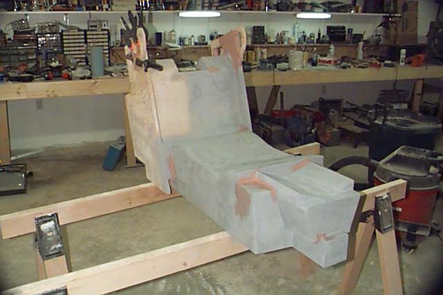
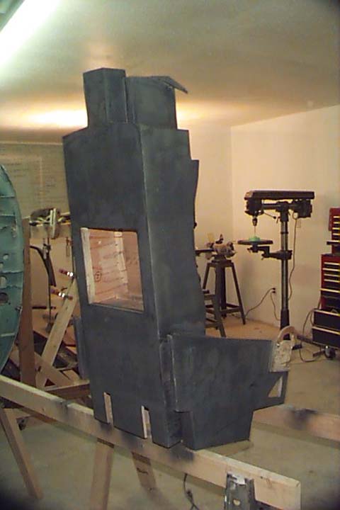
This is the ACES II replica that Rob & I built for the F-15. It was based upon Chris Van Lierop's great F-16 ACES II plans. We made the needed design changes as required by the current ejection seat mounting and model differences in the F-15 version of the ACES II seat. The seat was constructed from 1/2" and 3/4" plywood. The seat pan and back are made from 1/8" MDF (Medium Density Fiberboard). The picture below is a right side view of the seat. The faded pink coloring comes from the layer of Bondo that coats the wood. The whole seat was laminated with Bondo to give the seat a metallic feel as well as a smooth surface.

Here you can see how I built the ejection initiator handles. They're quite
simple and work quite well. The microswitches tie together electrically so
pulling either or both handles will "eject" you.
Here's a pic of the seat during the final sand & fill stages. The paint helps
to identify bumps & pits a bit more easily. This seat took nearly 6 weeks to
complete because of the extensive finish work that was done. The result is
very much worth the effor and 2.5 gallons of Bondo that was required.
Below you can see the first stage of painting. The ejection initiator handles
have been heavily varnished to seal the wood. Bondo was not used because the
very nature of the handle would lend it to being slightly bent or twisted and
Bondo would delaminate from the surface if this happened.
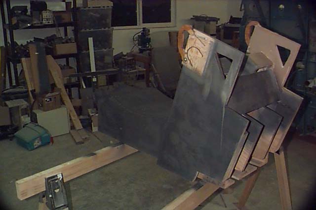
Here's the result of the first full base coat. The square cutout in the back
is where one of two sonic transducers will be installed. The cover for the
access cutout also holds the connectors needed to power the sound transducers.
The second unit is installed in the seat pan itself.
Here's the seat pan release handle before installation. This is _not_ a metal
handle! I obtained this finish by spraying the plywood handle with a few coats
of metallic silver paint. After this was allowed to dry completely, I put it
into a cardboard box and just *fogged* it with metallic copper. This picture
really doesn't do it justice. It looks great!
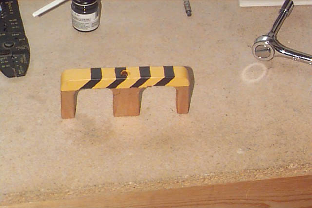
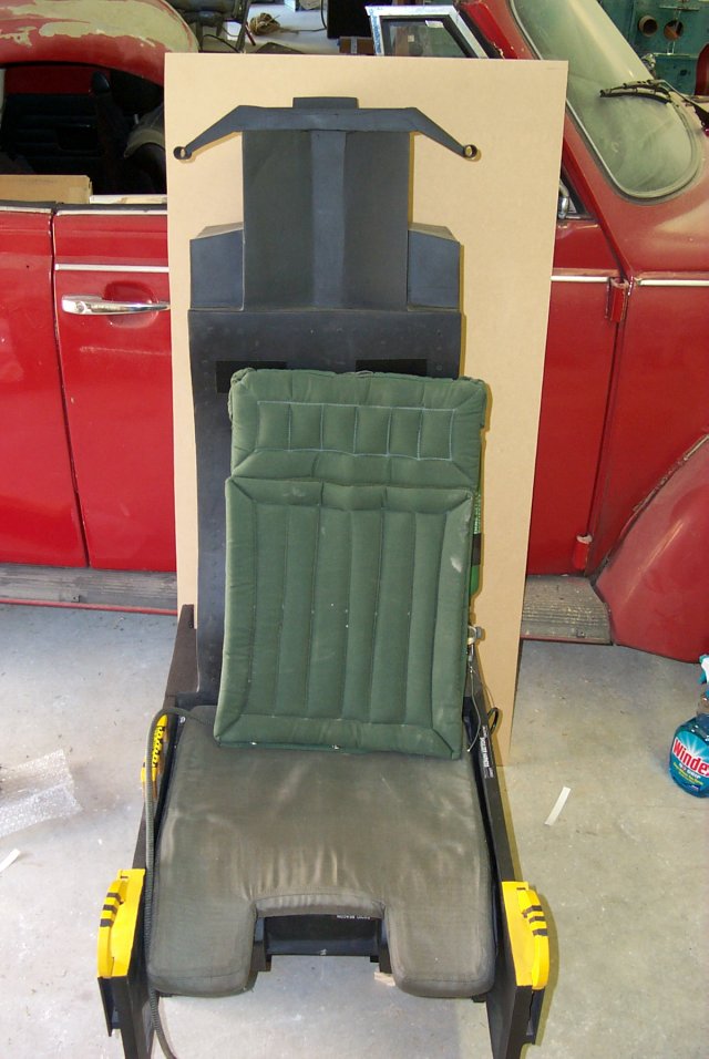
Here's the finished product. You can see the pan release handle and the
initator handles in their final state.
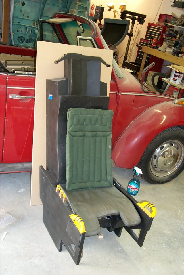
The oxygen bottle has been installed as well as some of the decals I bought
from AGT. I like text decals they make, but the ACES II badges need help.
ER kind of help. They have two months to live kind of help. :)
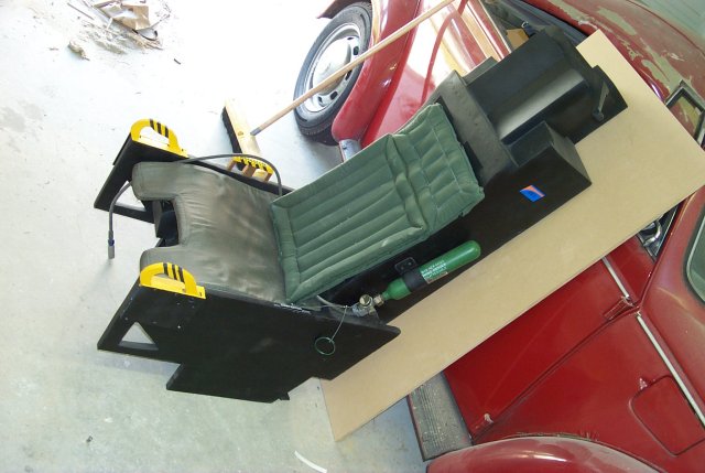
The seat pads are genuine ACES II pads. The pan pad is used and the back pad
is brand new. The back pad is held in place by a pair of velcro (visible)
strips.
All in all, this is one bitchin' bang seat. :)
This is the ACES II replica that Rob & I built for the F-15. It was based upon Chris Van Lierop's great F-16 ACES II plans. We made the needed design changes as required by the current ejection seat mounting and model differences in the F-15 version of the ACES II seat. The seat was constructed from 1/2" and 3/4" plywood. The seat pan and back are made from 1/8" MDF (Medium Density Fiberboard). The picture below is a right side view of the seat. The faded pink coloring comes from the layer of Bondo that coats the wood. The whole seat was laminated with Bondo to give the seat a metallic feel as well as a smooth surface.
Here you can see how I built the ejection initiator handles. They're quite
simple and work quite well. The microswitches tie together electrically so
pulling either or both handles will "eject" you.
Here's a pic of the seat during the final sand & fill stages. The paint helps
to identify bumps & pits a bit more easily. This seat took nearly 6 weeks to
complete because of the extensive finish work that was done. The result is
very much worth the effor and 2.5 gallons of Bondo that was required.
Below you can see the first stage of painting. The ejection initiator handles
have been heavily varnished to seal the wood. Bondo was not used because the
very nature of the handle would lend it to being slightly bent or twisted and
Bondo would delaminate from the surface if this happened.
Here's the result of the first full base coat. The square cutout in the back
is where one of two sonic transducers will be installed. The cover for the
access cutout also holds the connectors needed to power the sound transducers.
The second unit is installed in the seat pan itself.
Here's the seat pan release handle before installation. This is _not_ a metal
handle! I obtained this finish by spraying the plywood handle with a few coats
of metallic silver paint. After this was allowed to dry completely, I put it
into a cardboard box and just *fogged* it with metallic copper. This picture
really doesn't do it justice. It looks great!
Here's the finished product. You can see the pan release handle and the
initator handles in their final state.
The oxygen bottle has been installed as well as some of the decals I bought
from AGT. I like text decals they make, but the ACES II badges need help.
ER kind of help. They have two months to live kind of help. :)
The seat pads are genuine ACES II pads. The pan pad is used and the back pad
is brand new. The back pad is held in place by a pair of velcro (visible)
strips.
All in all, this is one bitchin' bang seat. :)
<P> 继续支持。</P>